Thursday, May 12, 2016

More on the Lowrance Elite 7 Ti

I guess I'll start out with the undocumented web browser interface I found. If you use a device that supports WiFi and web browsing then you can access this webpage. First pair up your device via WiFi like you do when using it with the Android or Apple Lowrance Go Free App. Then start up a web browser and type in the IP address of your unit. You should then get a page that looks like this:


The upper section is for uploading and downloading your Waypoints. Routes, and Trials USR file which resides in a protected area of storage. If you click the download button you end up with this:


This allows wireless transfers of this file directly to your device of choice instead of transferring it to an SD card and transferring it from the SD card to your device .... sweet

Basically these units are set up just like a smart phone or tablet. It runs Embedded Linux for ARM CPU's as it's core OS just like Android does, Also like Android, Lowrance has it's own custom GUI which gives it it's character but the hardware and storage memory is all controlled by the Linux OS. So just like an "Unrooted" or "Unlocked" phone or tablet the OS'es core file storage is protected from user access and you have a "home" directory that allows access to a small portion of storage for logging files, custom wallpaper, downloads from the Go Free website, etc. That's what the Logs section gives you access to. It's basically a simple FTP file server and when you click the "Logs" link you can see it's an FTP port. You can also access it via a FTP program by typing in the same IP address you used before and enter 21 as the port


Those folders are where you can download (or upload with a FTP program) your Sonar logs files and AIS files for those who have that addition to their system. If you click the parent-directory link it takes you up to the userdata folder which looks like this:


This gives you access to additional folders of interest like screenshots. Here's a little tip on how this undocumented feature can be used to many people's advantage. I can take a screen shot of something interesting I see on the finder. and then access it via my smartphone's web browser and then transfer the screen shot to Google + or Facebook or any other place you upload pictures. No messing around with transferring stuff to a micro SD card and then to my phone or tablet which is still tricky depending on the device. 
If you go up one more to the pseudo-root directory (Really a user's Home directory root) all you see is a folder marked 'userdata' but if you have an SD card plugged in you see this:

For some reason only known to a Lowrance engineer (or perhaps an oversight) it always displays 0 bytes for the SD card but you can click on it and access the files. I haven't tried it yet but theoretically I could delete a map and upload a new one via FTP and have a new map. I suspect I'll have to unplug and replug in the card to get it to read it though. Still that's a lot easier than fumbling around with a bunch of micro SD cards in a rocking boat ...... in the wind .... possibly raining .... etc.


As far as I know I'm the first to find this undocumented feature and the first to document it in detail. It does raise some interesting possibilities. I have a Nexus 7 2013 (Still one of the brightest LCD's out there) which I will use to display and control the Elite Ti remotely and I use a file manager program called ES File Manager and it has an FTP client built in so I can store scan logs, and maps on the Nexus 7 and transfer them back and forth to the Elite Ti with a few swipes of a finger. How cool is that?
As I mentioned in the previous post using the internal GPS for map making creates a sizeable error in the data so I reworked the NMEA multiplexer/GPS/logger I made last year to act as just a GPS with multiple outputs. I also reprogrammed the GPS to send all the messages the Elite Ti does such as $GPZDA which is just date and time but is apparently used by the Elite Ti to set the date and time on the unit. Because the Arduino's are fairly slow (16MHz) and the way they transfer data to an SD card I had to limit the data to 1 Hz but my unit is capable of 5 Hz so I reprogrammed the GPS for the faster rate. The output of the GPS module goes to one of the UARTS on the Arduino Mega and also to the same RS232 converter I used before only reversed, it's now an output instead of an input for a finder. I send that to the Elite Ti's NMEA 0183 input and the Elite Ti picks it up automatically and uses it instead of the internal GPS, no muss no fuss. The GPS data is sent to the Mega and output to the USB port and to a Bluetooth Radio so it can still be used without the finder. Here's a couple of shots of the reworked unit. I also upped the baud rate to 38400 which is the same 'official' baud rate for AIS (I plan on whipping up a little AIS receiver in the near future to monitor barge traffic when I'm fishing the Mississippi River) 


  The cost on this was a wash, basically the new parts cost about the same as the parts I removed and will use in another project. 
Initially frustrated by not having the NMEA 0183 data bridge over to the Wifi I decided I was going to try to make my own using the NMEA 0183 RS-422 outputs. Just a note, although I used the existing RS-232 converter to drive the RS-422 inputs I wouldn't recommend that with the outputs. If you ground one of the differential inputs (I used only one input and ground to ground) it may or may not work but you won't hurt anything, however grounding one of the outputs is a different story. Outputs without a load (grounded) tend to go up in smoke and even though the Lowrance likely has opto-isolated I/O it's still not a good idea. Besides getting the proper RS-422/485 to TTL (0-5V) converter is about the same price. I got mine from Fasttech.com out of Hong Kong for $1.10 
About a year ago I came across a neat little device designed by a Chinese manufacturer that looked very promising based on their ESP8266 WIFi IC. At the time people were still trying to translate the Chinese only data sheet and were hooking them to Arduino's and programming them via AT modem codes ( it has a 32 bit processor core and 512k -1Mb eeprom but no one knew how to program it until the English datasheets came out) The manufacturer released official datasheets in English last summer and development really took off so I figured someone had tried something like this even if it was for WiFi control of a different RS-232/422/485 device. So I headed up to the best place I know for info on the ESP8266 www.esp8266.com (of course)  And there I found this neat little project that was just what the doctored order .... I hate having to "redesign the wheel"  which is what I love about Open Source. So most of the following is credited to KB7KMO Larry Littlefield who is on a boat somewhere in the Pacific I guess. You can find more details on his version on his blog .

I made some minor changes to Larry's original design. First I dropped the switches because I likely won't need to reprogram the unit and if I do I can just tack in temporary jumpers. I set up my circuit on a breadboard first and programmed everything and verified it's operation and then mounted everything to a prototyping PC board. Larry used a single transistor circuit (shrewd) to convert the bi-polar higher voltage RS-232 signal to 3.3V logic levels. RS-232 signals also need to be 'inverted' since -12v is a logic high and +12v logic low which this single transistor converter does just fine (Converting from 3.3v or 5v to -12v to +12v RS-232 levels is a little trickier) The speeds are slow enough that about any General Purpose NPN transistor can be used here. However in my case I'm using a RS422/485 to TTL (5v) converter but I still need to convert the 5v TTL levels down to the 3.3v levels the ESP8266 needs. I could use Larry's single transistor circuit to do that except it inverts the signal and I don't want that. Now I could use a series current limiting resistor and hope the ESP8266 has "Clamping Diodes" to protect the inputs (It likely does) or I could make a simple 2 resistor voltage divider but the big downside to that is as the frequency goes up (higher baud rate) the capacitance in the circuit and input capacitance of the EPS8266 and the resistors starts to act as a lowpass filter which 'rounds off' the corners of your square wave signal which is never good for reliability. So I modified Larry's single transistor converter so it wouldn't invert the signal. All you really have to do to accomplish that is take out the NPN and use a PNP instead and change the configuration from Larry's common emitter setup to a common collector setup. I also changed the value of the pull-up resistors from 4.7k to 3.9k since I have a lot more of them and the value used isn't all that critical anything from 2.2k to 10k will probably work fine. It's a good place to use more uncommon values that you usually have more of left over from that last resistor assortment you bought. 5.1k is another good 'uncommon' value to use and pull-up resistors are a good place to use up some of those more uncommon values you have piling up since the value isn't all that critical, the next closest value will work just fine in most circuits. Anyways here is my version built on a slightly used Radio Shack prototype PCB (I really miss being able to drive 5 minutes and get stuff like this at a Radio Shack)


At the top is the ESP-01 WiFi module and the RS-422/485 to TTL converter. Below the ESP-01 is the PNP level converter transistor and the upside down module is a 3.3V LDO voltage regulator module.


One addition not shown is I added a pair of screw terminals like on the RS-422 board for the power leads in the open area of the PCB. I'll use some 2 twisted pair plus drain shielded data cable that I have but an old USB cable should work just as well in this instance (Don't toss those bad USB cords, cut off the ends and use the cable in your projects). Here it is mounted in a enclosure I made on my 3D printer (I love that thing)


Costs;
ESP-01 module - $3.15
RS-422/485 converter - $1.10
3.3V Regulator module - $0.85
2N3906 Transistor and resistors - $0.10
3mm hardware - ~$1.00 (I buy in bulk)
3D printed enclosure - $0.40
Total - $5.60

I'll make another post on how I set up a NMEA network on my Windows tablet which I set up as a hotspot/router that I can also access with my Android devices and grab the NMEA depth and position data from the Elite 7 Ti. 

Wednesday, May 11, 2016

New Mapping Setup and Lowrance Elite 7 Ti Review

After the first of the year I had a $1000 in my "Boat Improvement Fund" and knowing the HDS Gen 3 units were out and Lowrance was getting ready to end new production on the Gen 2 Touch I decided to see if I could find a setup for under a grand. While searching for deals on the Internet I stumbled across the just released Elite 7 Ti which was not only cheaper than the Gen 2 Touch it uses a single transducer for CHIRP, downscan and sidescan. Having a 16ft by 48" modified jon boat it was problematic get 2 transducers on the right side in 'clean' water and spaced at least 12" apart which is part of the reason I hadn't invested in a side scan unit.

For all practical purposes an Elite 7 Ti is a HDS Gen 2 Touch 7 without the ethernet outputs but does have the built in Go Free WiFi allowing it to be viewed on an Android or Apple smartphone and viewed and controlled with an Android or Apple Tablet (Unfortunately nothing for Windows Tablets but I have a workaround for that later) It uses the same SoC (System on a Chip) as the Gen 2, a NXP i.MX6DL which has a dual core ARM Cortex A9 microprocessor and fairly powerful GPU core with dual display outputs (one for the LCD touchscreen and one for the WiFi output streaming to phone or tablet) and hardware video decoding, a 20 bit parallel camera interface, USB interfaces, UARTS (NMEA 0183), 2 CAN bus transceivers (NMEA 2000) and a gigabit LAN core (Although there are no ethernet outputs the WiFi still needs and uses this core) I wasn't able to determine the speed but it's either 800 MHz or 1 Ghz. Basically the same basic setup as the HDS Gen 2 Touch. It also has a WiFi/Bluetooth combo radio but currently the Bluetooth hasn't been enabled and there is no interface/screen for it until they update the firmware (They were saying early 2016 but I notice that disappeared a couple of weeks ago) It also has RS422/485 level NMEA 0183 Input/output and a NMEA 2000 protocol port. Frankly as an EE who worked for an industrial process control manufacturer in the late 90's  I find the pricing on NMEA 2000 networking gear to be ridiculously expensive for a modified CAN bus that was developed over 30 years ago. 30 bucks just for a 2ft cord with 5 freaking wires in it that probably didn't cost even 2 bucks to manufacture in large quantities (> 100,000)  Can I afford it? Yes .... Will I pay that much, no freaking way. At best I'll buy a couple of the cords for the finders if I can find them cheap enough and build my own backbone

All in all it's a pretty responsive unit (granted I've only tested it it "on the bench" and haven't had it out on the water yet) and I've been able to make some decent maps for it since it allows control of 2-3 layers. For instance I can easily convert existing photo maps by 'tiling' them in Garmin KML/KMZ format and running them through Insight Map Creator which I can use as a shaded relief background which I can do live sidescans over or I can use it in the foreground and adjust the transparency for the isolines and depth labels to show through a vector depth map. Now I'll be able to log more than just depth and position but also hardness, downscan and sidescan data. Then I can play back and see exactly what I saw (or missed) while I was out on the water and then mark waypoints in the comfort of my own home on my main PC (Or play logs back in the finder itself)

However there are a couple of minor drawbacks that I had to make work arounds for. First is a problem every combo Finder/Plotter has. You have an error due to the transducer and the GPS antenna being so far apart, in my case about 8 feet. So if I am going from east to west and object on the finder is going to be marked 8 feet west where the GPS antenna is located. Now if I turn around and go from west to east the same object is going to log 8 feet to the east which is a total error of 16 feet. Now that may be OK for general use but for making maps it's just unacceptable. My depth mapping software can compensate for the error in software but it's a real nightmare to get and keep calibrated. So the solution I came up with back in 2010 was first using a USB GPS puck and an extender cable to place it over the transducer on the back deck which proved to work well as far as calibration and accuracy but the USB could be flaky and would often glitch when I started the motor. so in 2012 I went over to amplified antenna that are in some of the photos I posted last summer. So I basically reworked the multiplexer/logger/GPS unit I made last year and am sending just the GPS to the NMEA 0183 inputs on the Elite 7 Ti which automatically picked it up and switches back to the internal GPS if I turn it off. (Nice job on that piece of programming by Lowrance) I'll detail that unit in the next post (It also outputs NMEA position data to the USB port and a Bluetooth radio)

Then the other minor drawback although likely not a big deal for the vast majority of people is they didn't bridge the NMEA 0183 data to the ethernet and then stream it out a UDP port like on the HDS Gen 2 Touch even though the WiFI still uses the ethernet LAN core built into the i.MX6DL SoC. Basically all it would take is a few lines of code for Embedded Linux to bridge it to the LAN core but I guess since they dropped the ethernet outputs they wrongly thought it wasn't still an option. I've been messing around with a little WiFi module based on the ESP8266 WiFi chip and when I went looking for a way to use it by transmitting the NMEA 0183 output of the Elite Ti I found that someone had already beat me too it so I slightly modified it and it sends NMEA depth and position data to my main Windows Tablet PC which is set up as an Access Point/Hotspot which other devices can connect to (Like my Nexus 7 tablet running Open CPN) I'll also go into more detail on that device (I have under $10 in it) in my next post in a day or two. I'll also detail an undocumented web browser interface I found when trying to port scan the Elite Ti looking for the NMEA over WiFi. that allows some files to be transferred to any device that has a web browser and WiFi

Tuesday, May 3, 2016

The W.A.S.P - Details

I haven't made any changes to the unit over the winter since I got a new Lowrance Elite 7 Ti which has Structure Scan (AKA sidescan) so I don't know yet how much I am still going to need this for depth sounding in the flooded trees out at Lost Grove Lake (I have some new maps I'll be posting soon on my other blog) So I'll just document what I have already which works well as is.

The main drive for the unit are standard RC/Drone parts. The motors are A2212-13T 1000KV Outrunner Brushless Motors driven by a pair of 30 Amp brushless DC speed controllers. These are connected to a standard 2.4 GHz RC receiver which is controlled by a standard RC dual joystick controller used for planes and drones. These are powered by a pair of 11.1 V 2200 mAH lithium batteries in parallel. (Not shown )


Mounted in the round enclosure mounted on the stand in the back is a GPS receiver. Just below it is a bluetooth radio to send data back to my boat's computer or a tablet. 


Mounted on the front is an Garmin Smart Transducer  which outputs serial NMEA depth, speed and temperature which along with the GPS NMEA position data is sent to an Arduino Mega microcontroller with micro SD shield running the same NMEA multiplexer/logging program as the unit I detailed last year. The depth data is sent to one UART the data from the GPS is sent to a second, the main UART sends the combined data out the USB for debugging and the 4th UART outputs the combined data to the SD card and the Bluetooth radio. I log the Depth and Position to the SD card and send Depth Temperature and Position data back to the boat via the Bluetooth link.


Next up will be a short review of the Lowrance Elite 7 Ti and a couple of additions I made to improve the versatility of the unit.


Thursday, October 8, 2015

Coming Soon: The W.A.S.P.

The Wireless Aquatic Science Platform based around a project out of Spain called the JALC Boat. I have modified the design and added GPS and depth logging capabilities and will be doing a final design over the winter and hopefully also add APM (auto pilot module) to make it autonomous or RC controlled

Here are some quick shots I took the other day and I'll have more details after the season is over and detail the final upgrades I will make over the winter


Saturday, June 6, 2015

Trial Run A Big Success

Went out today for a few hours and did some calibration runs mapping depth in Dr Depth with the "Black Box" while using the Think Pad Tablet 2's internal GPS for general navigation. Depths were mapped using both the rear (main) transducer as well as switching to the one up front. Here are some pictures of it mounted and set up


Here is Dr Depth displaying position on a pre-existing map. Even in bright sunlight the PC Hood makes the screen bright and readable and even better than my old set up.


GPS antenna is mounted on the back deck (the hook part of stick on Velcro holds it to the carpet) almost directly about the transducer making calibration much easier


This is up front with the GPS antenna in storage position held on with Velcro


And here it is with the GPS antenna mounted on top of the navigation lights. There was a large tree stuck on the ridge of construction waste by the bicycle bridge and I was able to work around and map it with the trolling motor and front finder much easier than trying to do it with the rear transducer and motor, especially with a stiff breeze blowing right down the harbor. I won't use it a lot but it will come in handy in tight spaces like around the still standing trees in Lost Grove Lake.


I am very pleased with the new computer and set up with the ability to log both position and depth from the time I hit the water until I take it out. Well that's it for now but I do have some new picture of Lost Grove Lake I'll be putting up on the lake blog tomorrow. I estimate it has about 7-7.5 feet to go with rains coming this weekend and late next week. With normal rainfall for June which it looks like we'll have I expect it should top off in early July

Saturday, May 23, 2015

Depth Mapper in a Box, Weather in the Boat, and 3D Printer Magic

Let's start out with the "Depth Mapper in a Box".


The front panel consists of a red power on LED, a green GPS Fix LED, a power switch (USB power only) a SD card slot, a USB type 'B' jack and a barrel jack for power (7-12V)


On the back panel is a 2 conductor "microphone" jack for the NMEA serial output from one of my fish finders and the other is an SMA jack for an active (amplified) external GPS antenna


The internals consist of an Arduino Mega 2560 (clone) and Arduino compatible Data Logger shield that has the real time clock disabled (It gained 43 seconds per day rendering it useless) but is still useful because it has the level shifter (3.3v<-->5V)  needed for the SD card, a RS232 to TTL level converter for the Finder NMEA output and a uBlox NEO-6M GPS module. 


A closeup of the RS232 to TTL level converter which converts the +12V/-12V levels from the finder to the 0V-5V level used by the Mega. I'm only using the RX inputs and it is held in place with some 3M adhesive tape used in manufacturing


Here is a closeup of the GPS module. The PPS (pulse per second) output was configured to flash a green onboard LED when the GPS got a fix. I removed the resistor to the onboard LED and soldered a piece of 30ga, enameled wire to the pin 3 and wound a couple of turns of Kapton tape around the module to hold the wire in place. This feeds a resistor going to the front panel green LED as well as another resistor going to the Mega. I did this so on cold start up it doesn't start writing to the SD card until after it gets a fix.

The unit functions as a NMEA combiner/multiplexer and combines the $GPGGA, $GPRMC, and $GPGSA sentences from the GPS and combines it with the $SDDPT (depth) and $SDMTW (water temp) sentences and sends it out the USB port to my boat's tablet computer for processing. It also takes the $GPGGA, $GPRMC, and SDDPT sentences and sends it to the SD card as a NMEA.log file.

The unit can be used stand alone by providing 7-12V to the DC barrel jack or through the USB port using a cell phone charger or a rechargeable USB power booster battery and plugging in one of my finders and one of my antennas. I can also use it as a trip logger by placing one of the magnetic GPS antenna 'pucks' on the roof of my vehicle and plugging it into my cell phone/tablet charger. Basically I wanted to make a unit that automatically logs both position and depth from the time I hit the water until the time I pull out and without the need for a computer. This will serve mainly as a backup of data as well as a way to map even if I have a problem with the boat's computer.

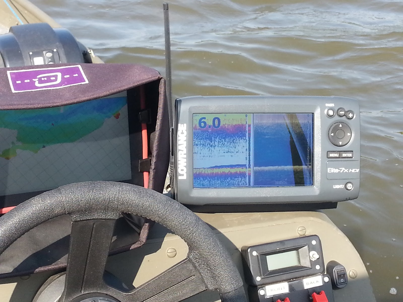
The reason I wanted to go with this route is I'll be running 2 finders, my Lowrance Elite 7x HDI with the transducer on the transom when I'm mapping using the motor and my old (well 5 years old) Garmin 300C up front with the transducer mounted to the trolling motor for mapping tight spaces like the dead trees out at Lost Grove Lake. I have an active GPS 'puck' antenna located above each transducer. All I have to do to switch from motor to trolling is turn off the GPS and swap the finder NMEA serial and GPS antenna connections and turn it back on. I'll mount it on the side of the boat under the console which brings me to the brackets I designed and printed on my 3D printer


This unit cost me $44.80 in electronics and $3.15 in PLA for the case and mount for a total of $47.95.

Next is a weather station for my boat which contains DHT22 temperature and humidity sensor and a BMP180 barometric pressure/altitude sensor which will be mounted in a small Stevenson Shield I printed


The sensors feed an Arduino Nano clone which will get power from and send data to the powered USB hub in the console. Here it is along with the sensors on a bread board during programming and testing.


Currently I have it programmed to send temperature, humidity, dew point, heat index and barometric pressure to a serial terminal every 10 seconds but I'll likely lengthen that to once per minute. I'll eventually send the data a fancier interface but my main intent is to grab the temp and pressure data along with the position, depth and water temp data from the combiner/logger and have it automagically insert that data into my fishing log/database when I open up a new record (I don't know if I'll get that last part finished yet this year).

I have a marine antenna mount on the side of my console that I'm not using and I wanted to mount to that but adapters are hard to find and expensive when you do so the 3D printer came to the rescue. The standard size and threads of a marine antenna mount is 1" 14 TPI so I went to the McMaster-Carr website and found a flange nut with those specs and downloaded the CAD files in STEP format, opened it up in FreeCAD, chose select all and exported it as an STL file that my printer's software can use. Then I just printed it out and it's a perfect fit


I found a neat little box on Thingiverse that you can resize and a holder for 8mm smooth rod used for the slides in a 3D printer and came up with this to hold the Nano and support a 8mm 2-3ft long fiberglass rod which the Stevenson shield and sensor will be mounted on.I epoxied the box to the flange nut and 2 of the 8mm holders to the box.


I'll mount the Nano on a perf board and make a hole in the side for the USB mini jack. Then I'll have a self contained unit I can mount/unmount to any marine antenna mount and in the case of mine I can fold it down for travel and flip it up for use.

Cost of electronics $10.70, PLA material $4.25 for a total of $14.95

The Arduino 'sketches' for both units can be found in the public section of my Google Drive:
GPS_Depth__Logger_Boat Weather.zip

Due to problems with Google Drive I've moved these files as well as the Lost Grove Lake preliminary maps to my GitHub repository:

Netbook2Chartplotter GitHub Repository

I'll take some more pictures after I get everything mounted and get it out on the water.


Thursday, January 29, 2015

Netbook2chartplotter Project: The Next Generation

Yeah I know it's kinda lame but it sounds better than the Winpad2Chartplotter Project although that's technicaly more true since I've upgraded to a Lenovo Thinkpad Tablet 2 ($300) running the Big Boy's version of Windows 8.1 Pro. It has a slightly faster but dual core Atom processor giving me roughly twice the computing power of the original, at least double the graphics and has capacitive multitouch along with a Wacom digitizer overlay and pen, a separate power/charge port, a full sized USB port and 64 GB storage/SSD. I added a 32 GB SD card and  I also got the fast charge dock ($100) which has 3 more USB ports and an HDMI out so I can just use a wireless keyboard/mouse and send the video to my 27" 1080p desktop monitor  and it's like working on a desktop computer (albeit a little slower)


I got the Logitech keyboard on sale but I would have gotten it regardless because it will fit right in the existing keyboard tray in the boat and can be held in place with Velcro, has a touchpad built -in and most importantly is part of their Unity line which means the USB receiver can work with any and multiple Unity devices at once. So I started looking for a Unity mouse on sale and a week later Best Buy had one marked down so I have it plus another receiver that will go in my boat (The other is in the dock) Also in the background is a 160 Gb hard drive from the old netbook that I replaced with a 120 Gb SSD drive that I mounted in a box with a USB to SATA converter in it, plugged into the dock and I use that to hold system restore and backup images as well as other data backups. I also got a thick rubber case to help protect and cushion it and it fits perfectly (with minor adjustments) in my Ram Mount system in my boat. The original Netbook2Chartplotter is still chugging along 24/7/365 sending weather and other data to some "Internet of Things" websites like the little applet in the upper right of the page showing the current (every 5 minutes) weather data here in East Davenport.

Finally after over 5 years from  my original conception I was able to find an off the shelf tablet **at a reasonable price*** that would meet my needs without any hardware modifications ..... Except one, an SMA input for an external antenna to simplify calibration by keeping the GPS receive location and the sounder's transducer as close as possible to each other both in back and soon in the front. The internal GPS and antenna is fine for general navigation and rather than modify the Lenovo and install a SMA jack (And it could be done mounted on the back where the space for the non-existent 4G modem) So how about something new, novel and custom .... An Arduino based NMEA multiplexer and SD card logger with built in GPS  and ports to hook up either the main or the front fishfinder so I can log postion and depth to the SD card as well as send it to the computer via USB (And likely Bluetooth too) for mapping. That way if I have a problem with the main computer I'll still be able to collect position and depth data for map making and the rest of the time it will serve as a backup. I also want to add a temperature/humidity and barometric pressure sensors and send that data to the main computer (And hopefully into my new fishing log/database automagically)


On the left sitting on top of the Nexus 7 in the Otterbox protective case (highly recommended for 'rough' outdoor duty) is the Arduino and GPS setup and on the left in the little breadboard is a BMP180 barometric pressure/altitude sensor and a DHT22 temperature and humidity sensor that I have already written the code for, I just have to hack in into multiplexer/logger code when it's finished.


The bottom layer of the stack is an Arduino (clone) Mega 2560 R3, the middle layer is a matching basic prototyping shield and the top is a data logger shield that's actually for the Uno R3 but works on the Mega with minor modifications. It has a 'realtime clock' (RTC) that's a complete piece of junk by all accounts and mine is especially bad gaining a ridiculous 43 seconds per day. I don't need it for this application because the GPS time is infinitely more accurate but unlike many SD card breakout boards it does have a proper level shifter IC which is essential for high speed writing to the SD card. So it's no good for the data logger application I bought it for but it works here and eventually I'll disconnect and disable the clock. So far I have the NMEA multiplexing code done and working so next is parsing the NMEA sentences ($GPGGA, $GPRMC, $SDDPT) I want to log to the SD card and writing to it which is going to be a little trickier


A couple of shots of the old Garmin 300C that will be mounted up front for mapping using the trolling motor. Since it has fixed speed (4800 NMEA standard) and you can't turn off individual unneeded messages I decided to use this to develop with rather than the Lowrance Elite 7x HDI which can change data speeds and you can turn off individual sentences. Besides the power harness for the 300C was already out (the transducer is already attached and laced up though). Here it is running in the demo mode sending data to .......


That little circuit board in the upper left which is a RS-232 to TTL level converter and then to one of the UARTs on the Mega. Below it is a uBlox Neo-6M GPS receiver module  with a SMA 'pigtail' hooked to a GPS antenna sitting on the sill of the basement wall which isn't exactly ideal but gets the job done


Here is the multiplexed GPS and sounder NMEA data in the Arduino's simple serial terminal


Here it is in Dr Depth and no I don't have a hole filled with water 82.8 ft deep in my front yard, however that is what the demo program on the sounder is reading and the location is spot on here


Here it is after 10-15 minutes and you can see the drift caused from the Doppler Shift due to poor antenna location and 2 large trees right out front of my house but this is no different than every other GPS I've used this way. Also I am unable to get WAAS lock which won't be a problem in my boat. Basically in my experience if it works good down here it will be outstanding in my boat.

That's about all for now and since I have a 3D printer kit coming later today I'm probably not going to do much developing on this for the next couple of weeks. Being able to design and print custom enclosures for my projects and make small plastic mechanical parts and mounts is going to be very handy not to mention all the other stuff you can just download and print if it catches your eye.