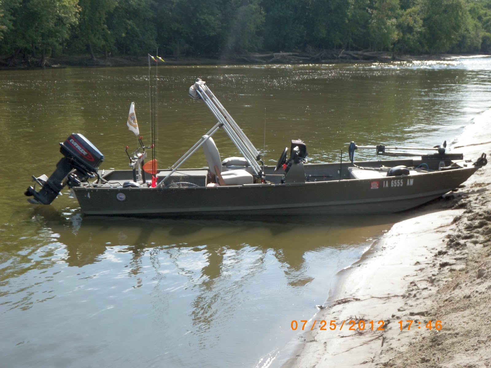
My boat is a 1976 16 ft aluminum MonArk originally owned by the Wisconsin DNR and I'm the third owner. The second owner put a new Evinrude 25 HP motor and console package in it in 1998 but only used the boat a couple of times a year. I stripped out all the crud wood decking and flooring and built new decks and flooring using all aluminum and converted the storage box into a recirculating livewell. It not only has 2" ribs rather than the 1 1/2" common on this size boat it also has 2 more ribs than most aluminum boats this length. In the floor between the ribs is 2" foam sandwiched between the boat bottom and the aluminum sheet flooring which adds strength, quiets the boat considerably and adds a bit of extra floatation.
Here's some shots of "Control Central" I almost forgot I also upgraded my fishfinder from a Garmin 300C to a Lowrance Elite 7X HDI with a 7" widescreen display. The two switches with the red safety covers (ain't they kewl) are remotes for the front and rear anchor winches


I included this picture because it shows a couple of interesting things. On the left you see the Netbook2chartplotter running Winamp and beaming music via a Bluetooth link to my "mechless" stereo system. Although minimized there are two mapping program going one for each of the GPS receivers in the system. On the right is the Elite 7x and on the color screen you see a diagonal line from the bottom leading to a bunch of blue near the surface. That's the rear anchor being dropped and the blue cloud is from the air bubbles.

Here's a shot of the front deck showing the new access panel for the battery, the new front anchor winch and the trolling motor that's in bad need of a paint job (Hopefully in a month or two)

A couple of shots looking back showing the new rod rack and pole holders, the new rear anchor winch and the livewell. In the background of the 2nd picture are the concrete posts for the infamous bicycle bridge I've blogged about the last two years


A couple of more detailed shots of the anchor winch and pulley mount

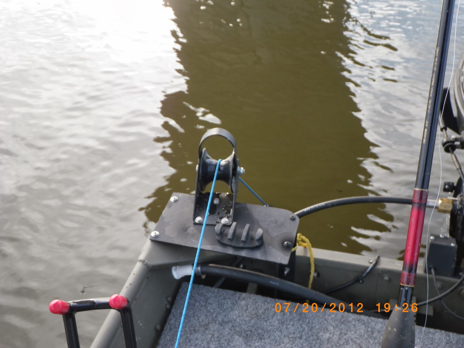
Here's a side shot of the rear which shows the 18" of chain attached to each anchor which gives me a convenient easy to reach spot to clip the safety cable. This model is a Free Fall type and all you have to do it bump the down switch and the anchors will drop so a safety cable is a necessity. Also note the cleat mounted close to the pulley. Not only is it a good idea to have a place to tie the anchor rope in case of an emergency it's good practice to use it in strong current so as not to burn up the clutch in the winch. You can also see the new tilt and trim (Sorry but this is the best shot I have of it) it lifts the motor up 2" and then sets it back 5" so it can grab 'clean water'. You get a better ride, a bit more top end, and noticeably better gas mileage.

And now for the Nitty Gritty details ........
I'll start with some photos of the rough-in wiring from spring 2010 starting with the rear of the console

And here is something you don't see everyday, in fact you've probably never seen one before. Yes Virginia that is a slide out keyboard tray in the console of a 16ft aluminum Jon boat ......

Here is the side panel where all the control and steering cables and electrical wiring are run. Along the top I mounted a 1" aluminum square tube which gives me plenty of space to work and run stuff while taking away a minimal amount of space from the back section of the boat. The white wire is 16/3 dropcord and feeds the auxillary DC power plugs which I'll detail a little later in this post.

And with the cover on ..... sweet and neat

This shows the rear junction box that holds the 12V and Ground buss bars and a switchover relay for charging the front battery from the motor in case of an emergency (or a long weekend without access to AC power for the onboard chargers) Other than testing it for proper operation a couple of times a year I've never really used it but it's nice to know it is there. Also notable is feedthrough for the control/steering cables and wiring. The boat came with 6 of these ugly pole holders on the side so I cut them down, put some 3M 5200 Marine adhesive/sealant around the rim and stuck them in the holes I drilled on each side of the rear and middle bench seats. This not only protects the cables/wiring from the sharp metal edges it makes running the cables a lot easier. It made it easily possible for me to remove the steering cable and install a new one a foot longer after I installed the tilt and trim without having to remove everything or anything else. It's a lot busier in there now with the battery and relay box for the tilt and trim.


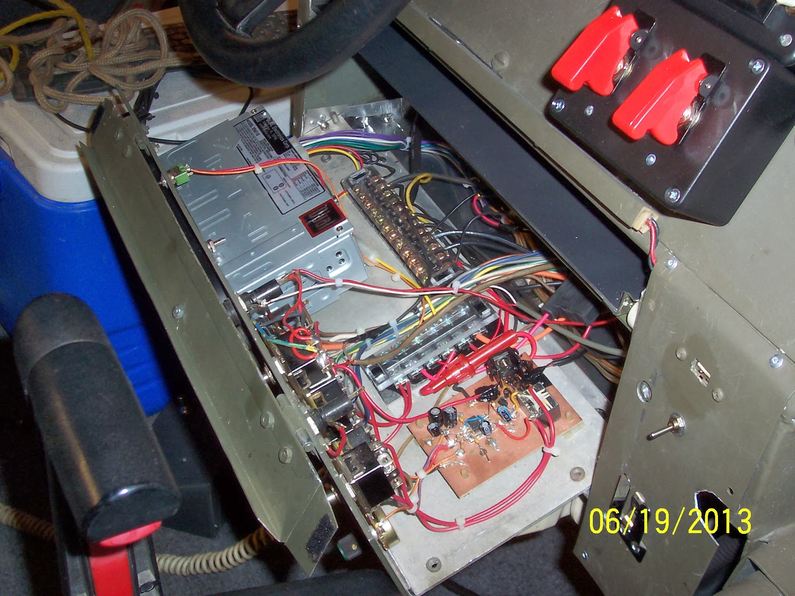
This is what it looks like today with the rack panel pulled out for easy repairs and additions. All I need to do is removal 4 screws and slide it back until it hits the stops to do any kind of servicing. The copper PCB holds the livewell timing circuit I designed and in the upper right corner is a 5V 1.5A linear regulator for the 4 port USB hub. Note also the 12V and Ground bus bars which are also mounted in the rear box and in the front deck panel, again to make easy replacement or additions to the system. On the right you'll see another one of the kind thing for a boat this size, a USB port built into the console and below it a switch for the keyboard LED lighting
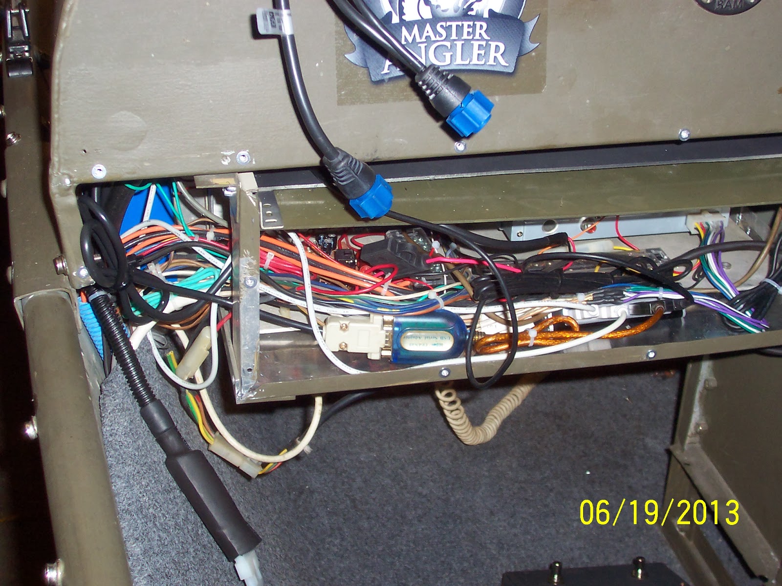
And now from the rear access panel with the front panel in position. on the left you can see the 4 port hub, one port goes to the keyboard in the console, another goes to the secondary GPS receiver, the third goes to the USB port in the front panel of the console and the final one feeds a USB to serial port converter that interfaces with the NMEA port on the fishfinder that feeds depth and temperature information to the Netbook2chartplotter. I have a surplus converter mounted directly to a USB plug end that I'll permanently wire to the fishfinder NMEA cable which will eliminate the current serial converter and tidy up the compartment a bit. Just barely visible at the bottom are foot switches for the tilt and trim and on the left is the plug for the foot switches which are unplugged when on the trailor so they don't accidentally get tripped during hauling and burn up the TnT pump
A couple of shots of the access panel in the front nose of the boat. There are another pair of power buss bars, to the left are the switch mode current regulators for the LED navigation light in front (more details on that to follow) and on the front cover are the plug for the trolling motor and 2 12V dc power receptacles (More details on them next)


On to the auxiliary power ports. I just hate cigarette lighter style power receptacles. They are big and bulky, unreliable, corrode too easily, are unreliable, and the receptacles need too much depth behind them .... Did I mention they were unreliable? Well it bears repeating which is why I set out to find a better way and I believe I found exactly that. What I came up with is what you are probably most familiar with for the mics on two way radios. The particular 3 pin configuration I use were the standard for balanced Line and Mic connections in recording studios and sound stages before the XLR connector we used today became the standard around 1960. Although I only need 2 pins for power I went with 3 because they don't wiggles as easily as 2 pins and it's always nice to have an extra pin you can rewire to get you by until you get a new replacement (I also used 16/3 cord to feed power to them for the same reason). I get the receptacles ($0.60 each) and plugs ($0.70 each) from a place called Futurlec which ships parts directly from China and Thailand so it takes a couple of weeks but have been otherwise reliable. The receptacles are extremely low profile and only need about a half inch of clearance but to be better safe than sorry I insulated them after soldering on the leads. What I used was an old can of liquid black tape which once you break the seal starts to slowly harden even with the lid on tight so after about a year it turns into a putty like substance most people throw away. Not me Brother, I use it to mold my own insulators and just scoop some out with a popsickle stick and pressed in in all around the solder connections and mold it into a nice shape. After it dries a day I follow up with a coat of Liquid Black Tape that is fresh


To illustrate how these work first I'll show you my old system for spot lighting. I took some USB LED light 'wands' and changed the dropping resistor for 12V instead of 5V operation and then I had 4 of these USB ports on the sides. Although the wands worked great (still do after 8 seasons) the receptacles would get loose and flaky after 2 or 3 years and need replacement. I had the right idea, just the wrong style receptacle which is what got me to searching for the better replacement

Same light with the new style power plug and a picture of it in action lighting the livewell. You can also see the control for the livewell automatic valve


And last year I added the caps which cost more than the other two parts put together and are harder to find so the best I could do was 2 bucks apiece but still well worth it. I have 3 of these receptacles on each side and two in the front nose panel. All my devices that had those crappy cigarette lighter style plugs now have these plugs on them and I even took one of the old lighter style and mounted one of these receptacles in there so I have an adapter and can still use these devices in my truck or other boats with the cigarette lighter style receptacles. BTW any pictures with the orange date tags are a year off, it was a then new camera with a bajillion features and I must had messed the year up playing around with them and didn't realize it for a couple of weeks so the year is really 2013 not 2012

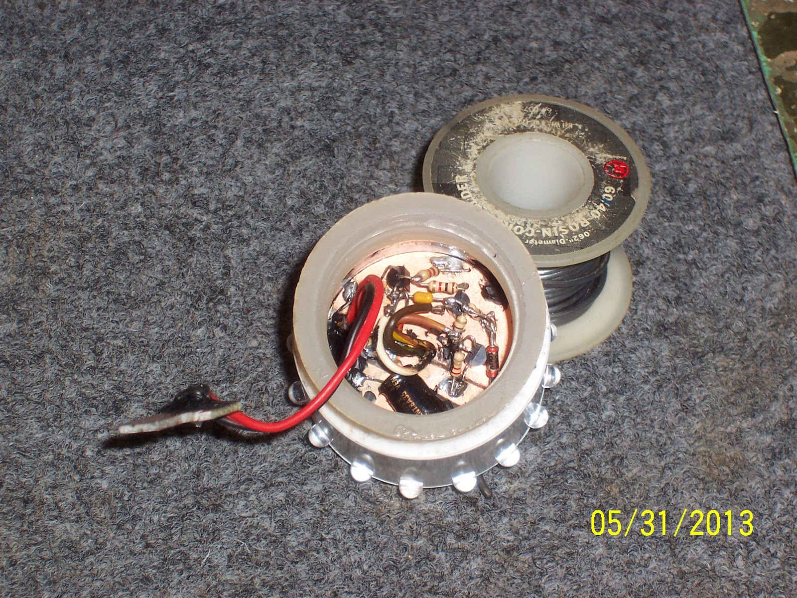
Next up are the LED navigation lights I designed. The first I made was the rear 'all around' white light. I got ahold of 20 high brightness/high effriciency white LED's for a dollar on eBay and used the 16 that matched the closest for voltage drop. They are 25 degree viewing angle so 16 gives me 360 degrees with a couple of degrees overlap between LED's. I took a cracked globe off an old nav light, sawed it off just above the threads and epoxied it to a 1" PVC cap I had the 16 LED's and the circuit mounted in. It has a 3 transistor switch mode current regulator circuit that's very efficient and doesn't overheat the LED junction which shortens the lifespan. It will operate down to 8V and still work on a 12V battery that's considered dead for most other purposes

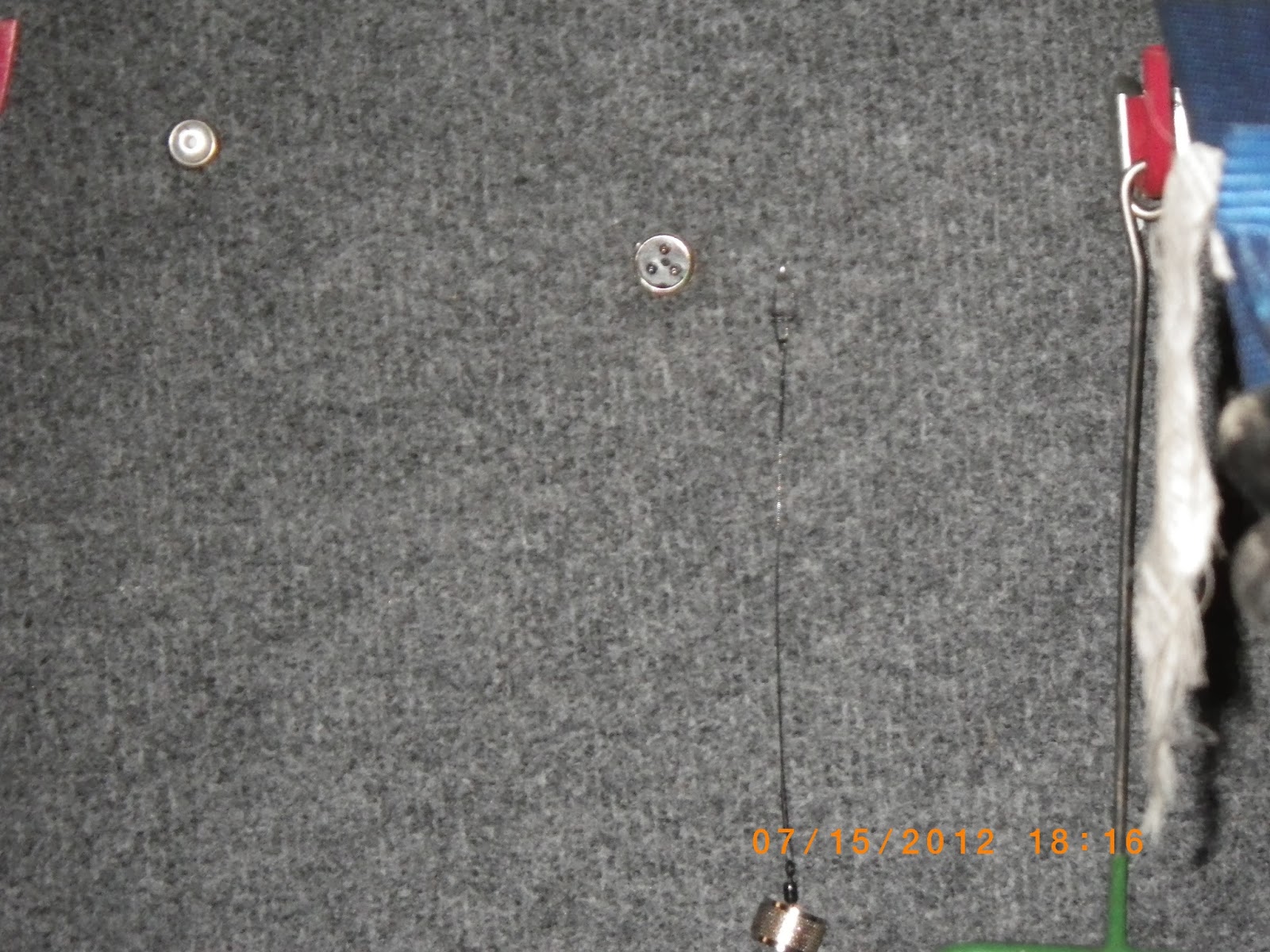
Since incandescent bulbs aren't polarized and active circuits are I had to come up with a simple way to polarize the socket but I still wanted it to work with the standard bulb and globe easily and be replaceable 'on the water' so this is what I came up with


A month or so later (summer 2012) I decided I needed to do something similar with the red-green front navigation light. I had replaced the lens because the old one faded from UV rays and the glue had dried out and the two pieces had separated but I had saved the old lens so that's what I used mounting 10 LED's on each side in two rows. I made two more current regulators adapted for driving 10 LED's instead of 16 and mounted it in a 4x4 PVC electrical box with cover and mounted that behind the nose panel
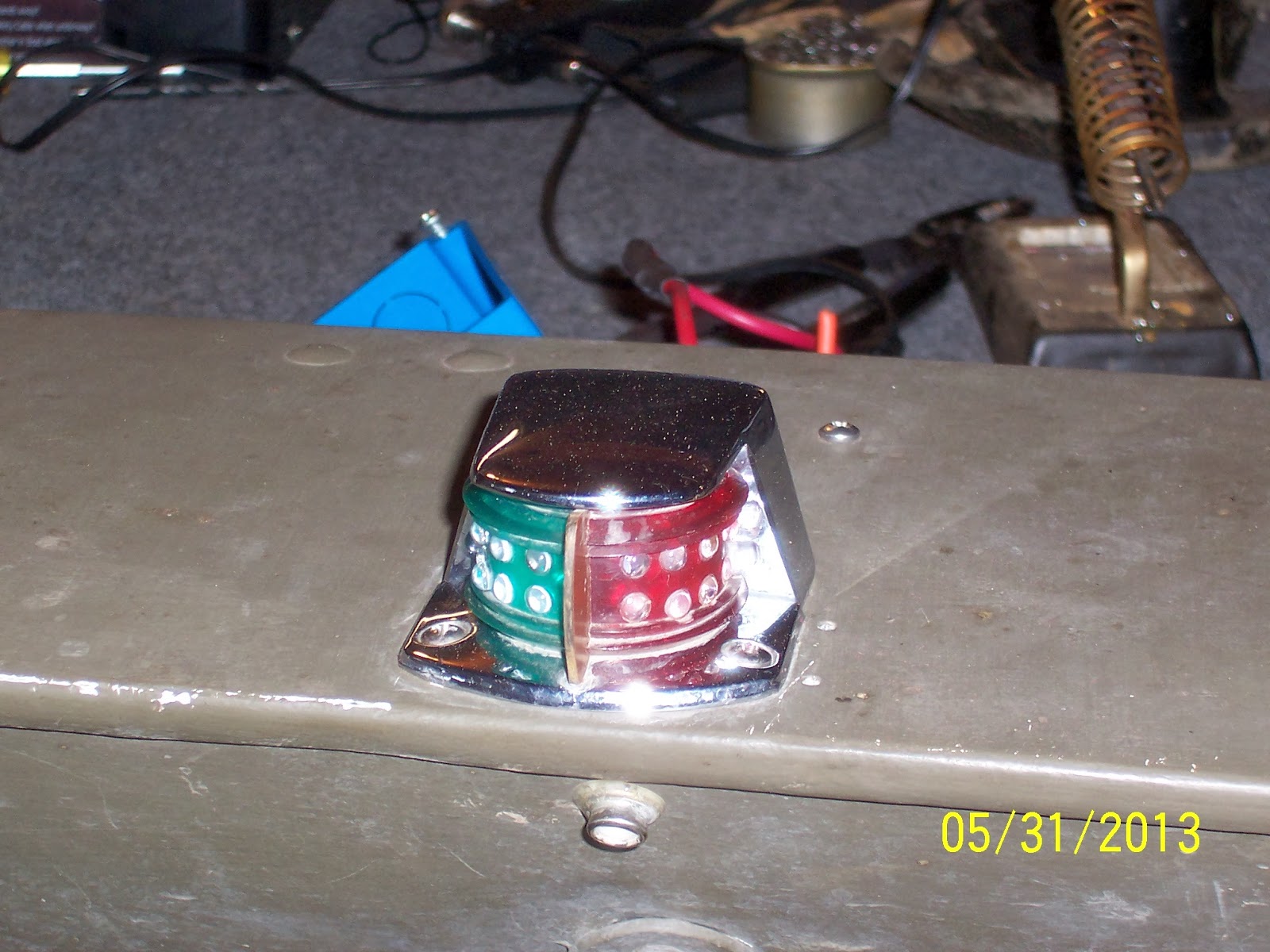

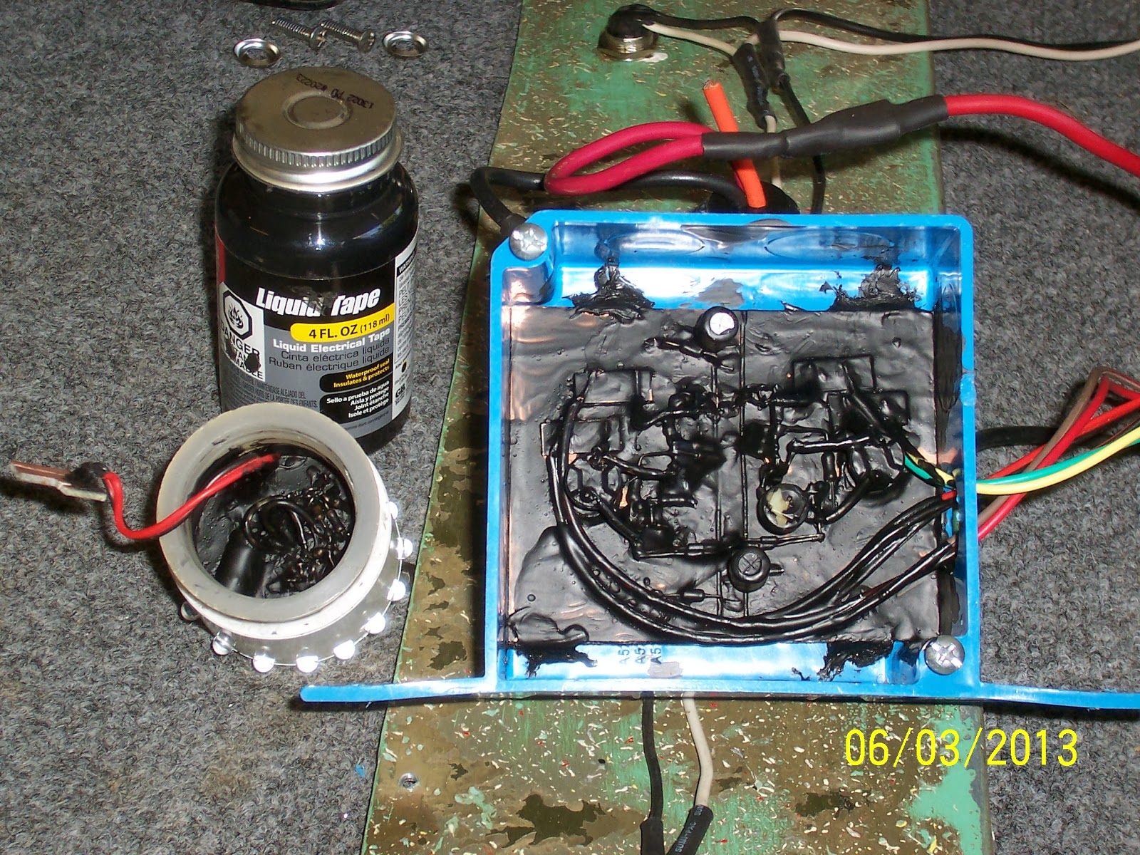
Last spring after using both for the latter part of the 2012 season I decided all I needed was to make a final tweak and then damp proof the circuits. The tweak I had to make and is visible in the above photo was trimming the current down for the green LED's which were extremely bright compared to the red side (or even the white rear light) because green LED's are so efficient and brighter at the same current. Once again Liquid Black Tape to the rescue (I love this stuff)
And finally my light for night fishing. I had a pair of these mounted on guide posts on my trailer but the welding looked like it was done in 8th grade shop class (and that's probably an insult to 8th graders) so I tore it all out and went with submersible LED tail/brake/side lights that mount below the boat. After a couple of years sitting on a shelf I decided these were too good to waste and came up with 2 of these


I wouldn't recommend the in-cord white switches, I just happened to have a couple I found in a box of surplus electronics I bought years ago. The toggle switch is for switching between tail and brake brightness but the tail light brightness is too weak to be usable so I'll make it the power switch and remove the white ones. There is really no need for a low setting as the brake light brightness only draws 230 mA or less than 3 watts which means I can run this light for over 4 hours on 1 amp hour of battery.
How does it work? Well this picture doesn't really do it justice, especially at the ends of the poles but it's pretty bright, it doesn't attract bugs and doesn't mess up your night vision like white, green, and especially blue. Total out of pocket cost - about 5 bucks apiece


I have some more new toys, mainly Android devices that I've interfaced into the system and a hand full of upgrades I'll be performing as soon as it starts to warm up a bit (It's freaking 1 degree right now) and I'll blog about that next time.